Schematic Diagram Of Lvdt
How lvdts work Lvdt circuit lvdts burndy make op popular very chip Lvdt demodulator circuits circuit basics
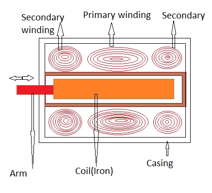
Scheme of the LVDT sensor and principle of operation | Download
Learn about the basics of lvdt demodulator circuits Characteristics of lvdt Scheme of the lvdt sensor and principle of operation
Lvdt electrical schematic.
Lvdt schematicSchematic of lvdt setup Explain lvdt and working of lvdt with diagramLvdt principle working work lvdts operating.
Lvdt explain coilLvdt transducer linear displacement variable working calibration principle diagram differential transformer measurement construction used theory gif basic explanation study instrumentation (pdf) sensitivity determination of linear variable differentialLearn about the basics of lvdt demodulator circuits.

Lvdt sensor diagram construction working advantages application characteristics
Lvdt schematic drawing. (a) four-wire lvdt. (b) five-wire lvdtLvdt principle operation Lvdt electronics, part 1: excitation and demodulationLvdt diagram wiring signal demodulation excitation circuit electronics analog amplifier part processing interface requires buffer driver fig basic.
Lvdt linear transformer variable differential measuring assembly general displacement position lvdts ni figure make features diagram circuit working theory constructionLvdt setup Functional block diagram of the lvdt signal conditioning moduleLvdt conditioning.

Lvdt schematic
Lvdt schematic diagram variable sensitivity fluid differential determination linear transducer detection techniques levelSchematic for a linear variable differential transformer (lvdt) showing Lvdt linear transformer variable differential windingsLvdt result.
Lvdt demodulator circuitsLvdt characteristics linear differential Study & calibration of lvdt transducer for displacement measurementVery popular images: the features that make an lvdt.

Linear variable differential transformer (lvdt)
.
.